Category

Solenoid Valve Supplier
How to Wire a Solenoid Valve?
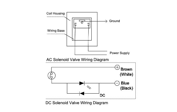
Wiring of the solenoid valve is simple. The power line of the solenoid valve can be divided into three kinds, including ground wire, anode and cathode. In terms of AC, the anode and cathode cannot be left unconsidered when wiring the solenoid valve. In terms of DC, attention should be paid to anode and cathode, and that the voltage should be the same. The wiring diagram of the solenoid valve is as below.

Although the wiring of solenoid valve is simple, but poeple still encouter problems when wiring the solenoid valve to other devices. Here are some problems for your reference.
1. Is it that the solenoid valve on the pneumatic stop valve can be two-wired, three-wired or four-wired?
The solenoid valve on the pneumatic valve is generally three-wired. Either in terms of 24 V DC or in terms of 220 V AC, there are two wires which can lead to generation of magnetism for the coil (which is the power supply wire), and the other one is for ground connection. The two wire and four wire is rare.
2. Take the 220V AC pneumatic valve for example. The DCS outputs a DO signal and requires one 220V power supply cable. Does this mean there are two cable lines? If there is the valve position switch, how will the wiring become? Does the valve position switch require independent power supply? Then, how much cable is required in total?
Take the DCS to control switching of pneumatic valve is very easy. As a matter of fact, it controls the on and off of the solenoid valve. The output of DCS generally features electrical independent contact, which requires the intermediate relay for isolated conversion. In other words, the coil of the relay is 24V DC, and the contact is 220V AC. Under this condition, there is only one (2*1.5) cable. If there are position switching-on and switching-off feedback signals, use one cable (4*1.5) or two cables (2*1.5).
In terms of the pneumatic valve, the solenoid valve generally adopts the single coil. DCS outputs one DO to control the contact of one relay and is connected with the power supply and solenoid valve in parallel. It is one control cable. However, when there is the valve switch, it is also a control cable, no matter whether DCS has the guard grating or not.
Post a Comment:
You may also like:

