Category

Solenoid Valve Supplier
Home » Application » PLC Controls a Solenoid Valve with a Relay
PLC Controls a Solenoid Valve with a Relay
The working principle of PLC controlling the solenoid valve is that output module of PLC switch value is connected to the coil end of the solenoid valve. When the corresponding point of the module has a voltage output, the solenoid valve coil is powered on and the contacts are attracted. When there is no voltage output, the coil is powered off and the contacts separate.
Wiring diagram of PLC controlling a 24V solenoid valve via a relay
The figure below is a wiring diagram of PLC controlling a 24V solenoid valve with a 24V relay.
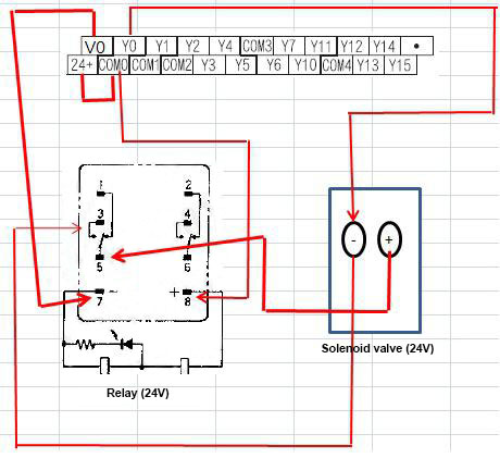
It shall be noted that if the PLC adopts the transistor output, COM of the output point shall be connected to the 0V. Then both transistor output and relay output are available.
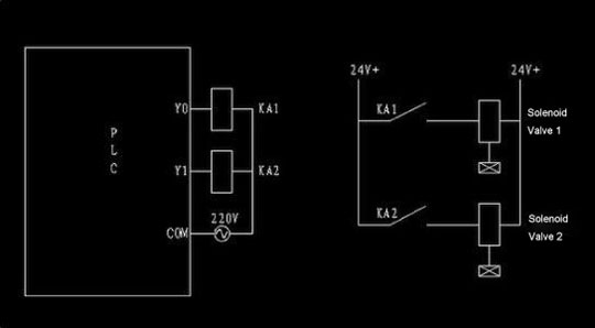
PLC [COM] connects to the negative terminal of the relay. PLC [Y0] connects to the positive terminal of the relay. One end of solenoid valve is connected with the common end of relay contacts. Another end of solenoid valve is connected with the normally closed end of relay contacts.
Drive circuit of PLC controlling solenoid valve
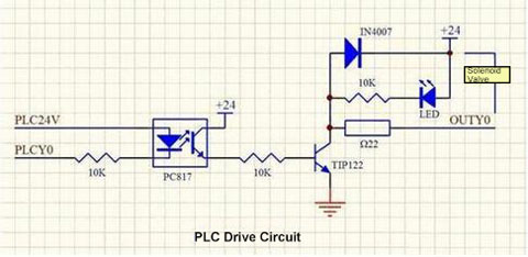
1. For light emitting diodes (including optocoupler devices), its current-limiting resistance should be selected to ensure that the current of the diode is between 8 ~ 10mA. If the current is too small, the luminous brightness is low (not bright). The light coupling effect becomes worse for the photocoupler because of the low luminous brightness. Therefore, the 10K resistor in the diagram shall be 2 ~ 3KΩ.
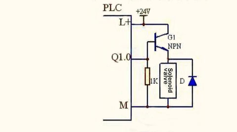
2. If the 24V power supply of PLC is the same power supply as that of the solenoid valve, the optocoupler can be saved. And a sane circuit as the figure can be drawn, thus greatly simplifying the circuit and reducing the fault points.
We know from the diagram that a Mitsubishi PLC is selected. The PLC output circuit adopts the negative logic, namely: positive pole of the 24V power supply is connected with the COM public point, and the output switch (the relay contacts or transistor switches) is connected with the output interface (Yn) and the negative pole of the 24V power supply. In this way, the transistor adopted should be the PNP type, and a simple output circuit is formed as follows:
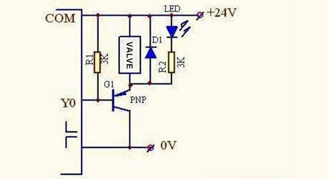
Optocoupler isolation is used in the scheme to protect PLC. When the solenoid valve is shorted, the protective resistor Ω22 may not be reliable, but the worst result is to burn out the switch tube TIP.
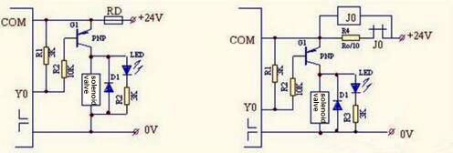
Change the circuit above into an amplifier, and then the output of PLC would not be burned out when the solenoid valve coil is short-circuited. The reason is that: R2 becomes the output load of PLC (10K) when short circuit occurs (current is only 2.4mA). By then, the excessive short-circuit current generated by the short-circuit coil will endanger the 24V power supply, and the following two circuits can be used to protect the power supply for over current and outage:
1. Connect the fuse RD in series in the circuit (refer to the left diagram). In case of a short-circuited coil, excessive current will disconnect RD and cut off power supply.
2. In G1, a resistance R4 is connected in series between the emitter and 24V power supply. Resistance value of R4 is equal to one tenth to one twentieth of the solenoid valve coil resistance. Then, a 24V relay is connected in parallel with R4, and R4 is then connected with the normally closed contact of J0 relay (see the right diagram below). In normal cases, Y0 = 1 (output = 0V), the G1 is conducted, voltage of R4 is about 1 ~ 2V, and voltage of the solenoid valve is 22 ~ 23V, so the solenoid valve can operate normally. J0 would not be attracted because of low voltage. If the solenoid valve coil is short circuited, the circuit becomes the emitter follower circuit: by then, voltage of J2 is 24V, J2 is attracted and its normally closed contact is disconnected. Cut off R4 to avoid the circuit to generate excessive current. Then close its normally open contact to send the signal for short circuited. The relay is used for protection because the coil short doesn’t occur frequently, so the service life of relay is not considered.
Wiring diagram of PLC controlling a 24V solenoid valve via a relay
The figure below is a wiring diagram of PLC controlling a 24V solenoid valve with a 24V relay.


Drive circuit of PLC controlling solenoid valve


2. If the 24V power supply of PLC is the same power supply as that of the solenoid valve, the optocoupler can be saved. And a sane circuit as the figure can be drawn, thus greatly simplifying the circuit and reducing the fault points.
We know from the diagram that a Mitsubishi PLC is selected. The PLC output circuit adopts the negative logic, namely: positive pole of the 24V power supply is connected with the COM public point, and the output switch (the relay contacts or transistor switches) is connected with the output interface (Yn) and the negative pole of the 24V power supply. In this way, the transistor adopted should be the PNP type, and a simple output circuit is formed as follows:

Change the circuit above into an amplifier, and then the output of PLC would not be burned out when the solenoid valve coil is short-circuited. The reason is that: R2 becomes the output load of PLC (10K) when short circuit occurs (current is only 2.4mA). By then, the excessive short-circuit current generated by the short-circuit coil will endanger the 24V power supply, and the following two circuits can be used to protect the power supply for over current and outage:
1. Connect the fuse RD in series in the circuit (refer to the left diagram). In case of a short-circuited coil, excessive current will disconnect RD and cut off power supply.
2. In G1, a resistance R4 is connected in series between the emitter and 24V power supply. Resistance value of R4 is equal to one tenth to one twentieth of the solenoid valve coil resistance. Then, a 24V relay is connected in parallel with R4, and R4 is then connected with the normally closed contact of J0 relay (see the right diagram below). In normal cases, Y0 = 1 (output = 0V), the G1 is conducted, voltage of R4 is about 1 ~ 2V, and voltage of the solenoid valve is 22 ~ 23V, so the solenoid valve can operate normally. J0 would not be attracted because of low voltage. If the solenoid valve coil is short circuited, the circuit becomes the emitter follower circuit: by then, voltage of J2 is 24V, J2 is attracted and its normally closed contact is disconnected. Cut off R4 to avoid the circuit to generate excessive current. Then close its normally open contact to send the signal for short circuited. The relay is used for protection because the coil short doesn’t occur frequently, so the service life of relay is not considered.

Post a Comment:
You may also like:

